At the start of 2023. NLnet decided to sponsor the development of BB3-CM4.
As we mostly designing HW and we need to comply with EMC standards and regulations we decided to run some in house
experiments to find or design affordable opensource equipment for pre-compliance measurements.
https://nlnet.nl/project/BB3-CM4
Previous articles
To get an insight into what we are doing in this experiment, please check the preview articles.
In the first one, we have a quick introduction with the equipment we are using.
We also did scans with near-field probes.
https://intergalaktik.eu/news/bb3-cm4-emc
In the second one, we created two chambers, one from an old microwave, and the second from compressed cardboard sheets isolated with aluminum tape.
https://intergalaktik.eu/news/diy-emc-chamber
In this one, we will have one more design that we will need to test.
Anechoic chamber
Our goal here is to create an anechoic chamber for our in-house EMC pre-compliance tests, but what is an anechoic chamber?
An anechoic chamber (an-echoic meaning "non-reflective" or "without echoes") is a room designed to stop reflections or echoes of either sound or electromagnetic waves. They are also often isolated from energy entering from their surroundings. This combination means that a person or detector exclusively hears direct sounds (no reflected sounds), simulating being outside in a free field.
https://en.wikipedia.org/wiki/Anechoic_chamber
Targeted shape of the chamber
Me and emard have talked a lot about what shape would be easy to assemble and use for measurements.
At some point, we found that GTEM CELL has a pyramidal shape.

So we have decided to go with the pyramidal shape.
Simulation of the pyramid
emard wanted to do some simulations first.
He wanted to check if the pyramid would prefer some signals as that would not be acceptable.
He has used Python to generate the NEC file that we can now open and check inside Xnec2c.
Xnec2c is an open-source high-performance multi-threaded electromagnetic simulation package to model antenna near- and far-field radiation patterns for Linux and UNIX operating systems. The original FORTRAN version of NEC2 was ported to C by Neoklis Kyriazis, 5B4AZ, and released as nec2c. Later he wrote xnec2c, a graphical interface for ease of use with many more features.


From the insides of the pyramid, he used the properties of a special material that we will need to find to get the least possible reflections.
Xnec2c showed that the chamber would not "favor" any frequency we want to measure.
For our measurements, we would be satisfied if we could measure signals from 30MHz to 1GHz
Creating a pyramid in OpenSCAD
So emard opened openSCAD and did all the designs!
We want a chamber that is easy to assemble and disassemble as most of us do not have much room to store big boxes, so he decided to add magnets for easy opening and closing assembly.
Each peek of the pyramid has an antenna, and we could use those antennas to measure the DUT (device under test) from different angles without rotating.
You can find Python, NEC, and OpenSCAD files here: https://github.com/intergalaktik/EMC-experiments/tree/main/EMC-pyramid
In OpenSCAD design, you can select what parts of designs you want to render, as some are for printing and some for cutting.

Let's build a pyramid!
Now we have simulation and designs, so let's cut, print, and build.
First, we cut the pyramid sides.
For this, I have used the MDF as I get it with each PCB stencil order.
We can also print antenna holders.
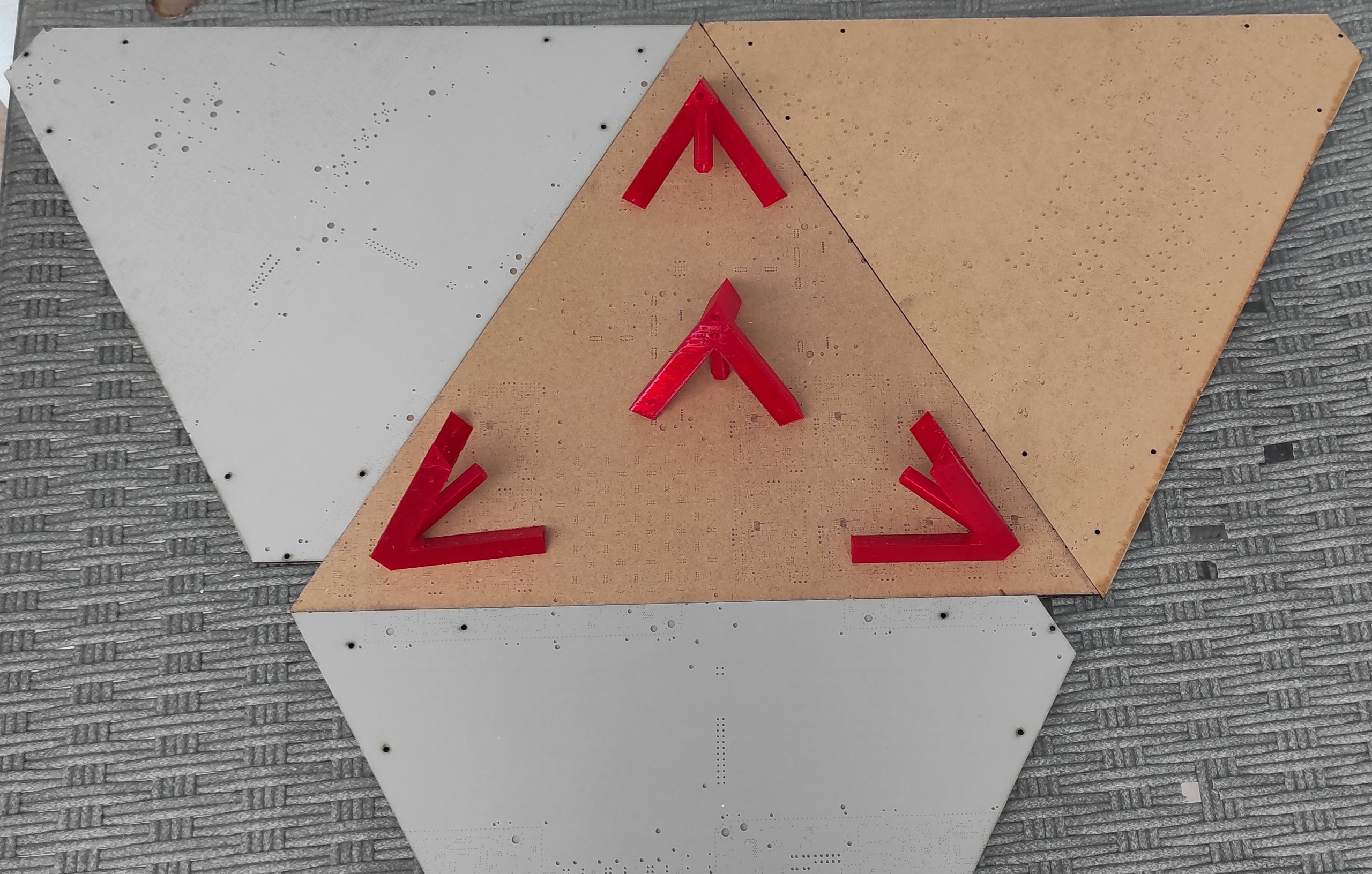
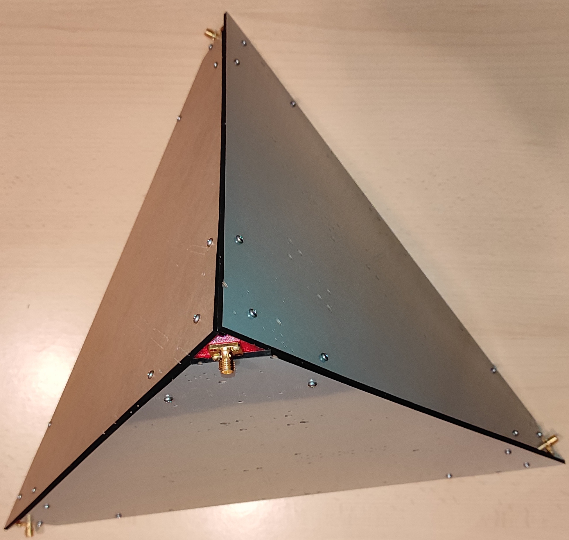
Pyramid - version 1 - with screws
MDF is smelly to cut, but I have been stocking this wood for a long time, and now is the best time to use it.
On v2 designs, I have added big holes with a diameter of 10mm. It is now easy to put tape on one side, then place magnets, then close the other side with tape.
Isolation
After magnets are in, you can isolate each side with aluminum tape.
I have also tried to cut and isolate cardboard.
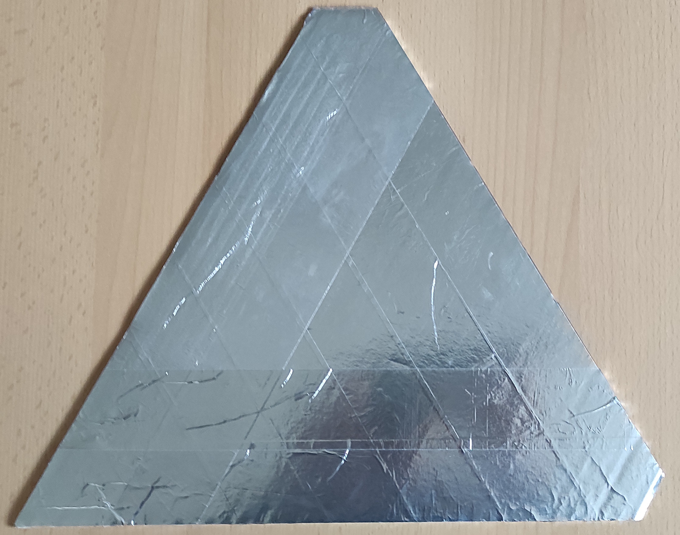
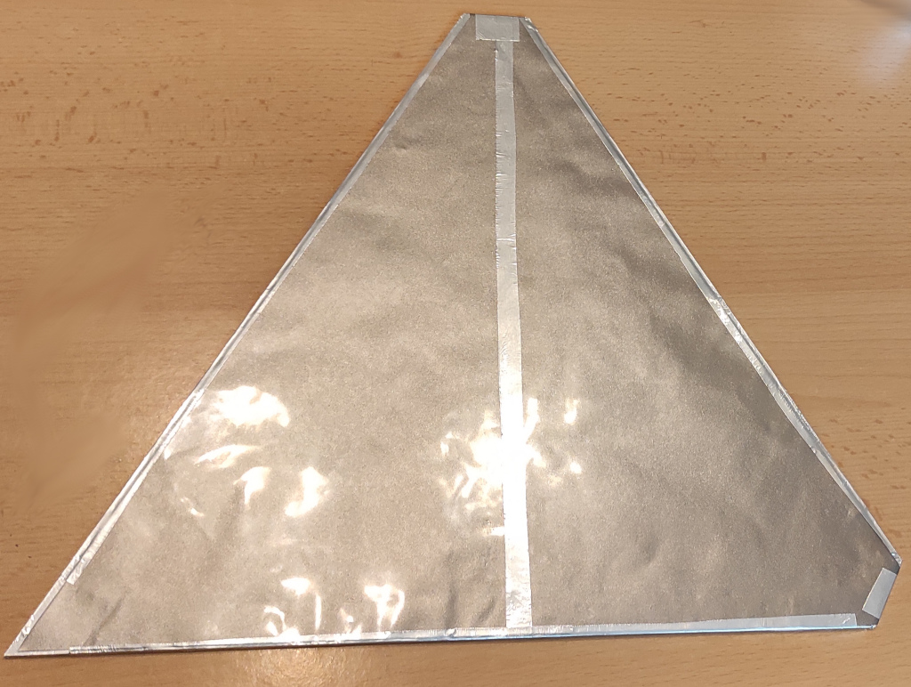
On the other side, that will be turned into the device, we need to place special absorbing foil.
From the datasheet you can see that it has lots of useful features:
Hybrid construction consisting of both magnetic and conductive layers
Provides for attenuation via magnetic losses and noise magnetic flux absorption within the magnetic layer
Provides reflection (blocking) and Eddy current losses on the conductive layer
Available with top insulation layer or top conductive layer (which can be grounded)
Available on a roll or in sheet form
Easy to cut/punch to the required size and shape
We will cut the foil in a specific way so that we only use one foil sheet per the pyramid side.
Foild link: https://github.com/intergalaktik/EMC-experiments/blob/main/EMC-pyramid/empyr02.pdf
Take two foils side by side and use this PDF for cutting instructions.

Then tape the foil on the pyramid sides.
You will need to use aluminum foil on the edges and in the center to connect the two parts.
The magnetic side of the foil needs to point inside the device.
DUT holder
We also need to cut a PCB holder - to have the PCB in place.
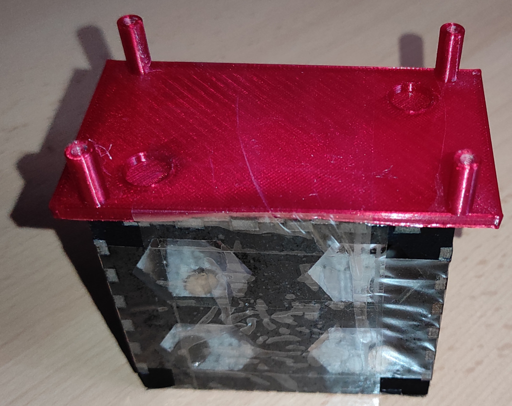
I have also placed magnets on it, so it will hold still and always be in the same place if I add magnets on the bottom of the pyramid.
How easy is full assembly?
Assembly of the pyramid is now super easy; without any problem, you can assemble and, in a few seconds, disassemble the complete unit.
You can now start assembling from the bottom side of the pyramid and "throw" antennas on the corners, then add any side, add the top antenna, and then add the remaining side.
Measure everything
For real measurements, we would need to measure the real amplification for our frequency range.
With current equipment that is possible and I will do it once everything is set up - for now, I will assume amplification of 25dBm on all frequencies and add that to my tinySA calculations.
Data on the web page shows this:
This is a broadband LNA with a low noise figure. The PGA-103+ chip is produced by Mini-Circuits. It is a modern generation of ultra-linear low-noise monolithic amplifiers with ultra-high IP3, high dynamic range high output Power, and low noise figure. To ensure that the maximum dynamic range and linearity are achieved with the lowest possible noise figure.
28 MHz = G 22 dB -NF = 0.70 dB
50 MHz = G 25.7 dB -NF = 0.55 dB
145 MHz = G 25 dB -NF = 0.50 dB
435 MHz = G 20.4 dB -NF = 0.62 dB
1090 MHz = G 14 dB -NF = 0.80 dB
1296 MHz = G 13.2 dB -NF = 0.85 dB
2320 MHz = G 7.5 dB -NF = 1.7 dB
1. Using PGA-103+ chip design;
2. Working frequency: 50M-4GHz;
Measuring materials with two probes and nanoVNA
In our last article, we used two tinySAs for measuring how blocky material is, but Nemanja from X suggested I try nanoVNA.
So let's do it!
First, set the range on your nanoVNA - in my case that is from 10MHz to 3GHz.
Then do a full calibration on your device!
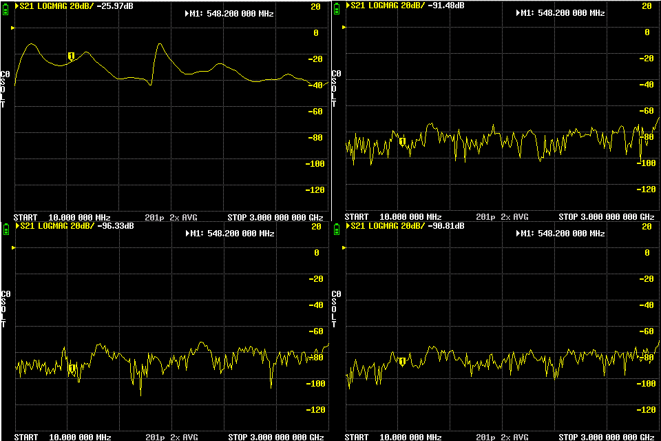
Leave just one trace and set measurements to S21 - connect probes to nanoVNA and get measurements without any material.
You will nottice that measuring S21 with nanoVNA is much faster then measuring with two tinySA devices.
Then place the material and take measurements again.
The difference between those two measurements is how blocky the material is...
Those are measurements I got with the amplifier ( I did not add external amplification to the VNA so it is not showing it )
The only thing visible on those graphs is that I did not amplify signals enough and that most of the signals did not pass any barrier ( aluminum foil, special foil, and both) as the graph should look the same just with a big drop in signal.
Back to the box and pyramid
First, comparison results show that a pyramid did perform a bit better than a box, but for that, I needed to tape most edges. I only left two edges untaped so I could open and close the pyramid, but super easy assembly and disassembly are now not possible.
The yellow trace is a box and the green trace is a pyramid.
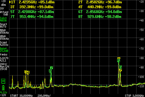
For better visibility, we need a graph from EEZ studio

Both scans took around 10 minutes and TinySA was set to collect the MAX signal.
It is visible that the box (yellow trace) did capture some higher signals than the pyramid.
Only at some frequencies, are having a bit higher peaks on the pyramid.
Signal in a quiet environment?
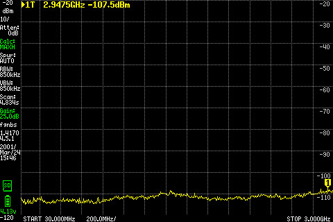
I also did a test in my basement inside of the pyramid, and 10 minute scan showed that the signal is under the noise floor, so I do not see anything except noise!
So I will need a better or additional amplifier to check how blocky the pyramid is!
Almost completed pyramid!
Ok so now we know that pyramid is good let's add ULX3S!
This was a picture with 20 cm antennas - emard is suggesting 5cm - 10cm.
Upper measurements are with 15cm antennas.
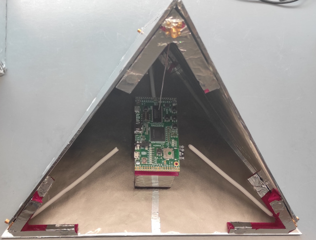
Added edge covers, as that makes slight improvements.
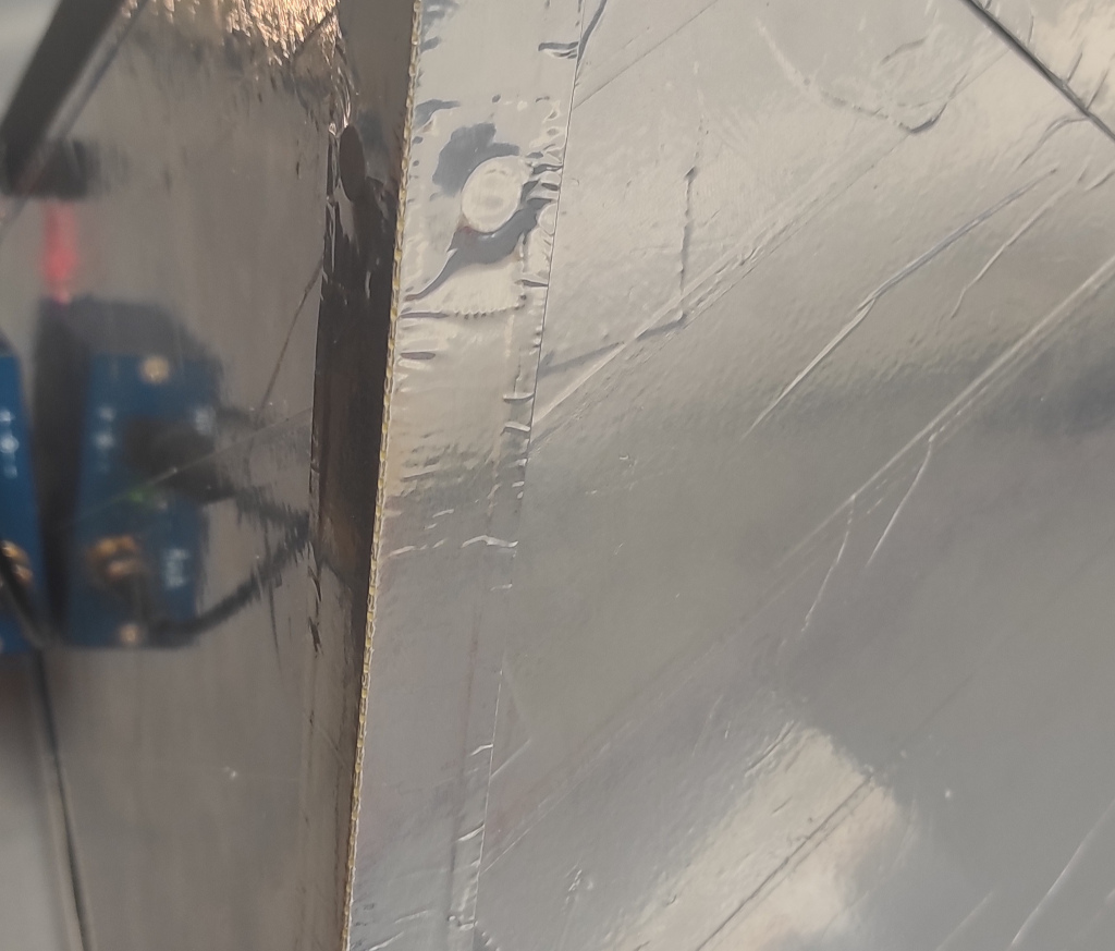
Last minute improvements
In my last article, NLnet also pointed me to this link https://esp32-open-mac.be/posts/0003-faraday-cage/
The author of that article is using a special material called titanRF to block signals.
As in a noisy environment, I still see signals getting in I ordered two packages from Amazon.
https://mosequipment.com/products/titanrf-faraday-fabric
It arrived in a fancy package
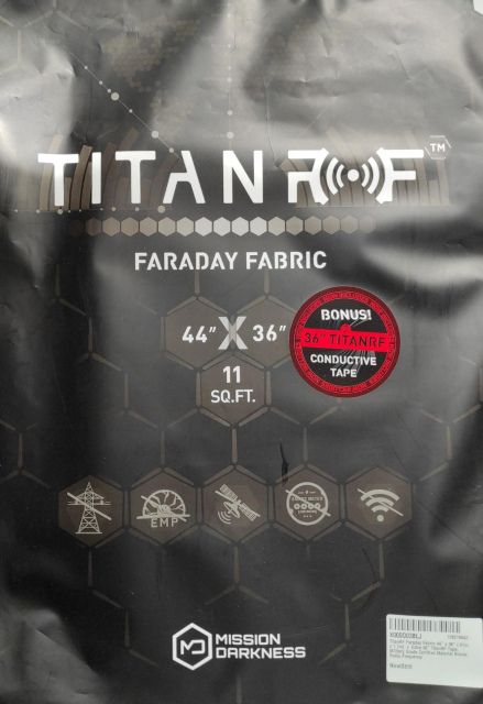
It also looks nice

It arrives with some promo papers that claim MIL-STD 188-125 standard and shows a graph with more than 80dB attenuation on all frequencies from 0MHz to 5GHz if just a single layer is used.
That is even more than we need for our box.

So I have just covered my first box as it is easy to just throw a blanket over the box and then on the pyramid and here are the results.
This was done in my noisy environment!

Those are measurements done with TinySA Ultra with a 25dBm pre-amplifier connected.
On TinySA I have set up that signal that has an additional 25 dBm gain so this shows real signal strength.
Red trace
opened box door - it is visible that the noise is high, for example, the Wi-Fi signal is over -65dBm
Green trace
closed box door - it is visible that there is less noise, but you can see that the Wi-Fi signal is still over -83dBm
Blue trace
fabric over the box - wifi is now at -104dBm everything else is just under noise flor!
Next steps
I think that this type of antenna (wire) is not perfect for this job; we would need some directional antenna to pick up all noise from the device.
Emard already has the idea of creating a better antenna.
We first experimented with just a ping pong ball covered with aluminum.
After that, it was just aluminum foil compressed into a ball that was on top of the antenna.

After some thinking, emard designed an antenna like this.

Our next plan is to simulate all those antenna types, maybe even do some fancy Blender animations...

For that purpose, we can use openEMS + Octave + Blender.
openEMS is a free and open electromagnetic field solver using the FDTD method. Matlab or Octave and Python are used as an easy and flexible scripting interface.
Once we get antennas simulated, maybe we could also simulate complete chambers and discover if we have more flaws in designs so we could make it better!
Summary and Conclusion
Building a box and adding foil is much easier than building the pyramid, but the once-assembled pyramid is easier to assemble and disassemble, even if you would need to cut foil between edges and tape again for the measurements.
The signal with the gain we have is now fully blocked, so we would need a better amplifier to get better measurements.
We have assumed amplification of the amplifier, and for real results, we will need to measure it and manually add it to measures.
When TinySA is set to a high range from 10MHz to 3GHz in our case it may not pick up every signal - so for better accuracy, we would need to take multiple measurements with a lower range, and then combine those measurements.
Even if we did get better measurements with the pyramid we will need to confirm those with multiple measurements and in different conditions as we could just get lucky in this case.
It would also be perfect if we could confirm our results in simulation and a certified laboratory.
Even if we create a perfect antenna we would need to calibrate it, and then add antenna gain/loss after the measurements.
At this point, I am satisfied with both chambers and think we will get even better and more reliable results in the future.
I have learned a lot, but in the magical RF, there is always a completely new world of knowledge waiting for me.
Add on ...
I am slowly making improvements in EEZ Studio application.
And first thig I want to do is to measure the gain of the amplifier.
I have connected my other tinySA to do sweeps with known power, in this case that was -50dBm.
Second device was just logging MAX of the received signal.
Once you have that graph ( my scan took about 1h ) you can connect your TinySA to the studio, get a graph and calculate GAIN.
If we compare measured GAIN with seller description it looks that we got the same GAIN.
Conclusion: I need better amplifier :)
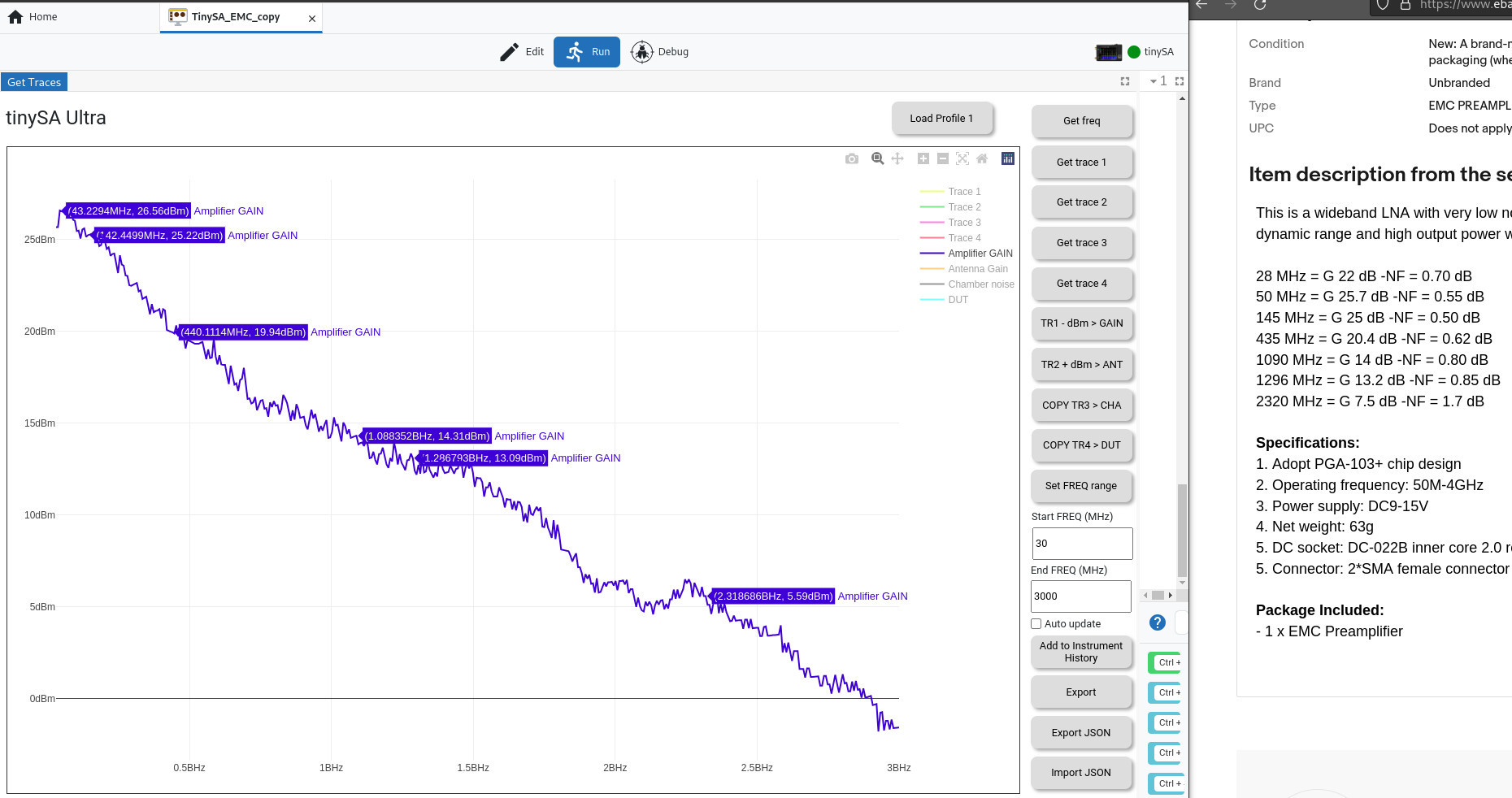
You can also see that I have added few more options that I still want to polish!
External links that you want to check
https://www.testandmeasurementtips.com/pre-compliance-emc-testing-6-ways-your-project-will-benefit/
https://emcfastpass.com/pre-compliance-chamber-options/
https://www.ema-eda.com/store/pcb-products/tekbox-tbst86-49-45-2-b-small-emi-shielded-tent/
https://picclick.it/GTEM-CELL-250-TEM-WAVEGUIDE-CHAMBER-IMMUNITY-EMI-295056446248.html
http://www.nextem.co.jp/web/english/emcproductsj/shieldedroomj/shieldedroomj.html
https://www.kebamerica.com/blog/emc-considerations-in-electric-vehicle-applications/
https://interferencetechnology.com/how-to-build-your-own-emi-troubleshooting-and-pre-compliance-kit/
https://interferencetechnology.com/diy-near-field-probes-preamplifiers/
https://interferencetechnology.com/wp-content/uploads/2012/04/Wyatt_NA_DDG12.pdf
https://www.emcesd.com/tt2019/tt021419.htm
https://blog.michalhrouda.cz/2020/06/making-tem-cell-for-emc-measurements/
https://github.com/PetteriAimonen/tem-cell
https://github.com/PetteriAimonen/tem-cell/issues/1
https://www.testups.com/diy-rf-anechoic-chamber/
https://www.edn.com/emi-pre-compliance-test-with-a-microwave-oven/
http://joshstone.us/wiki/#!2020-01-04-pattern.md
https://www.emcfastpass.com/test-equipment/shop/antennas/horn-antenna-tbma4/
https://www.emcfastpass.com/test-equipment/shop/antennas/biconical-antenna/
https://www.ebay.com/itm/154671521064
https://design-4-emc.com/tag/antennas/
https://www.eevblog.com/forum/testgear/diy-biconical-antenna-30-300mhz/
https://www.eevblog.com/forum/testgear/howto-calibrate-diy-emc-pre-compliance-antenna/
https://vandersonpc.com/Diy-HF-Current-Probe/
https://theemcshop.com/emc-emi-test-setup/ground-reference-plane-for-emc-emi-testing/
https://jestineyong.com/make-your-own-emi-measurement-probes/
https://www.uniteng.com/index.php/2013/05/30/measuring-emi-with-homemade-magnetic-field-probe/
https://m.youtube.com/watch?v=2xy3Hm1_ZqI
https://github.com/dezanche/H-field_RF_probe
https://github.com/umcu7tcoillab/EMI-probes
https://github.com/ketszim97/NearField_PCB_Probes
https://github.com/GregPlusPlus/Near-Field_Probes
https://github.com/oh7bf/NfHprobe
https://www.rtl-sdr.com/creating-an-emc-probe-using-an-rtl-sdr-and-semi-rigid-coax/
Project link
https://github.com/intergalaktik/EMC-experiments
Contact
Radiona/intergalaktik discord: https://discord.gg/qwMUk6W
Envox discord: https://discord.gg/btKVC5sedG
Many thanks to NLnet for sponsoring our work!
By: Goran Mahovlić
This project is funded by NLnet https://nlnet.nl/project/BB3-CM4/
This project was funded through the NGI0 Entrust Fund, a fund established by NLnet with financial support from the European Commission's Next Generation Internet programme, under the aegis of DG Communications Networks, Content and Technology under grant agreement No 101069594.


You might also like
-
DIY-EMC-chamber
- Written by Intergalaktik d.o.o.
- Published on
-
BB3-CM4-EMC
- Written by Intergalaktik d.o.o.
- Published on
-
BB3-CM4-H7
- Written by Intergalaktik d.o.o.
- Published on


